Our Solution
What it Does
Our solution is an indoor environmental monitoring system that tracks multiple metrics, including:
- Temperature
- Humidity
- Gas (VOCs)
- Carbon Dioxide
- PM 1, 2.5, 10
- Sound
This will give the user (likely students and educators) a full picture of their indoor environment. This information will be visible on a display for easy viewing and monitoring. Multiple display views will be available to the user.
Technological Aspects
To realize our solution, we will be using an ESP32 based board (Adafruit Feather V2) in combination with multiple sensors, such as:
- BME 680
- SCD-40
- PMSA003I
- ICS‑43434
An LCD display will be used to show the collected data. We will leverage I2C, I2S, and SPI to facilitate communication between the sensors and the Adafruit ESP32 board. For power, we will use both the 3.3 volt pin and 5 volt pin (+ an LDO) from the ESP32 board. All power and communication needs can be met with minimal extra hardware.
Testable Hypothesis:
Our indoor monitor will correctly measure and display the temperature, humidity
CO2, PM 1, 2.5, 10, and noise levels in a classroom environment. Specifically,
we will be able to detect when the CO2 levels are above 1000 ppm which is when
cognitive performance starts to become impaired in the classroom environment.
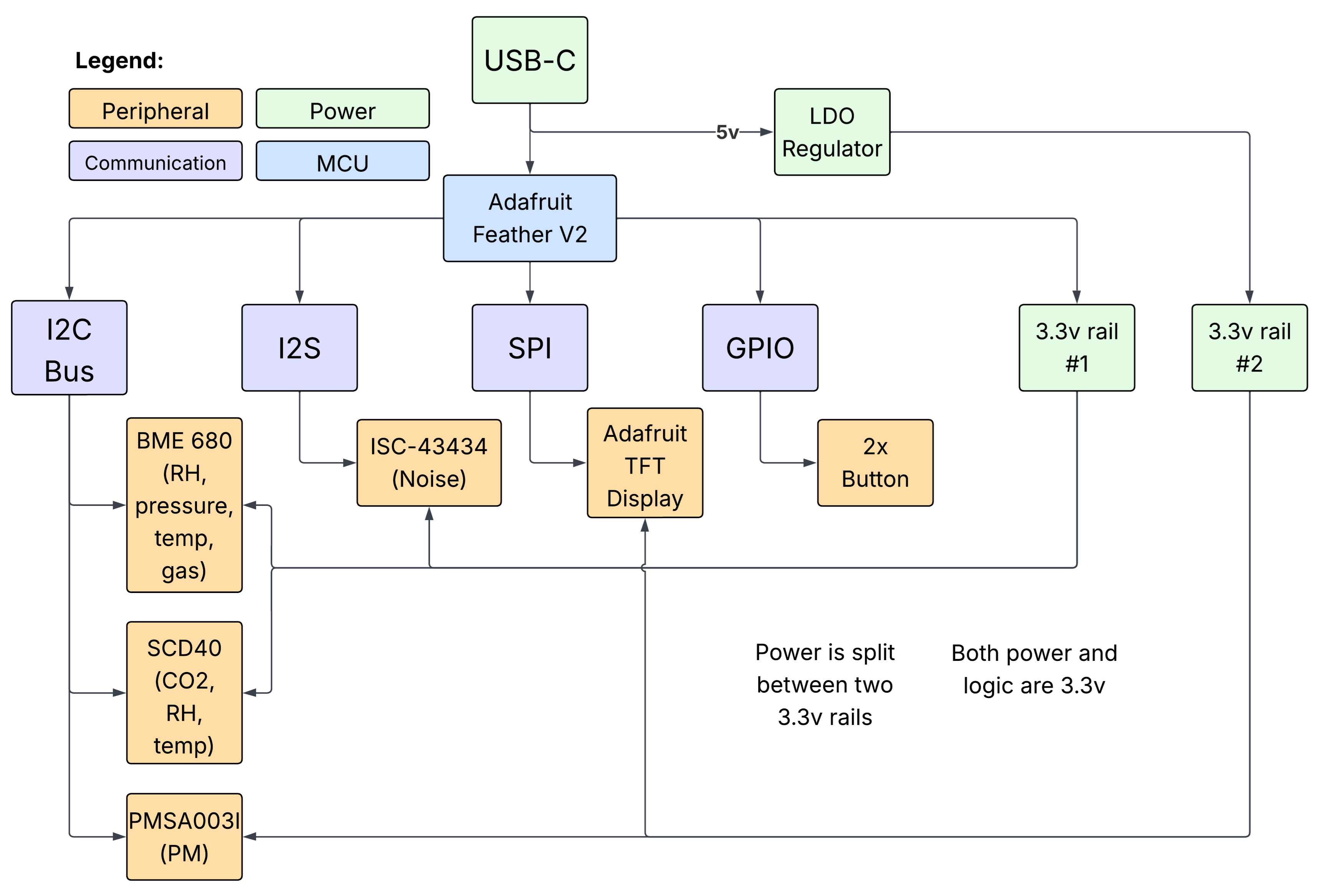
Block diagram including microcontroller, sensors, and display
PCB Design
Our PCB is integral to our project as it connects our various environmental/sound sensors, display, and buttons to our Feather V2 (esp32) board. Once it is assembled the PCB will be housed in a 3D printed enclosure, which will physically be our final solution. The PCB connects everything together which allows for sensor measurements to be taken and displayed, the user to use the buttons to switch views, etc. which is our entire functionality.
Thankfully, our PCB design and assembly was actually quite straightforward. Due to quadruple checking our design prior to ordering, we were able to avoid any issues and everything worked as expected after assembly. Two things that required extra consideration were:
- The fact that the esp32 input only pins do NOT have pull-up resistors, so we had to add them to our PCB
- The 3.3v regulator on the Feather V2 cannot power all of our sensors, so we needed to use an LDO to create an extra 3.3v rail
These two considerations were the things that *could have* gone wrong, but thankfully we were able to catch them. Otherwise, we didn't have any major challenges or pivots in our PCB design or assembly.